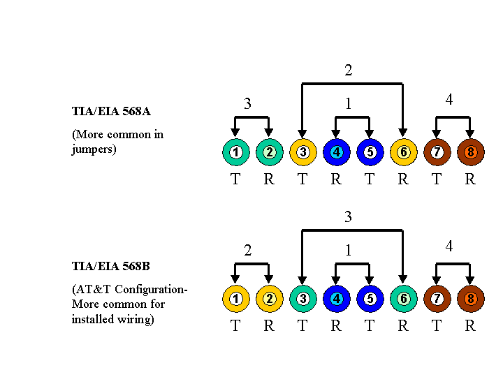
Both 568A and 568B wiring schema are widely used for terminating pairs in network infrastructure within category 5 cabling systems. Each pair has two strands of conductors known as the Tip and the Ring. On our diagram, T and R are used to denote Tip and Ring. According to the color scheme, each pair has a wire of solid color and a wire with a white stripe. The Tip wire has the stripe, the Ring solid coloration. When the conductors terminate in a jack pins are assigned according to the schema associated with the 568A or 568B template.
See diagram below for graphical representation of the schema.

When designing and installing a network, one scheme should be selected and consistency maintained throughout for ease of maintenance and the prevention of errors. 568B, the AT&T configuration, is the preferred system because of its consistency with most installed telecom infrastructure. That said, a combination of systems is possible provided any given cable is not started with one system and ended with another.
From a technical standpoint, both 568A and 568B use pin/pair assignments that offer transmission performance advantages over other Category 5 wiring configurations.
