110 Block Installation Instructions
 |
 |
 |
 |
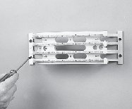
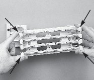
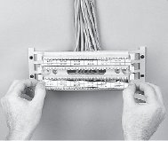
| Mount the 110 wiring block and legs onto a suitable mounting surface with the necessary screws and hardware. | Remove the 110 wiring block from the legs by depressing the outer 4 fanning strips. Pull the 110 wiring block away from the legs. |
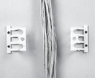
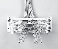
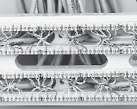
With the 110 block removed, route the cable between the legs. | Lace the cables through the appropriate openings in the 110 wiring base and snap the 110 wiring block back onto the legs. Push the wiring base onto the legs until the latches “snap” into place. |
 |
 |
 |
 |
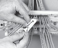
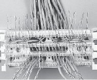
| Strip back only as much cable jacket as is necessary to terminate the conductors. | Lace the conductors into the 110 wiring base. Pair twist must be maintained to within 12mm (.5") of the point of termination for category 5E installations. Ample channel space is provided to allow jacketed cable to continue close to the point of termination. | Seat the conductors and trim off the excess wire with the cutting edge of the impact tool. | Visually inspect the conductor and cable placement at this point to eliminate any miswires or reversals. |
 |
 |
 |
|
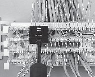
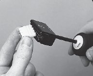
| Insert a 110C connecting block into the head of a 5 pair impact tool. |
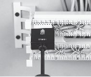
Carefully align the 110C connecting block over the wiring base, with the blue marking to the left side of the block (gray stripe down), and seat the connecting block. | Label the circuits then slide the designation strip into the 110-HLDR and snap the holder onto the wiring base. |
